How Hotpatching on Windows Server is changing the game for Xbox
Learn how Microsoft has been using Hotpatch with Windows Server 2022 Azure Edition to substantially reduce downtime for SQL Server databases.


Deploy a cloud application quickly with the new Microsoft SDN stack
You might have seen this blog post recently published on common data center challenges. In that article, Ravi talked about the challenges surrounding deployment, flexibility, resiliency, and security, and how our Software Defined Networking (SDN) helps you solves those challenges.
In this blog post series we will go deeper so you’ll know how you can use Microsoft SDN with Hyper-V to deploy a classic application network topology. Think about how long it takes you to deploy a three-tier web application in your current infrastructure. Ok, do you have a figure for it? How long, and how many other people did you need to contact?
This series focuses on a deployment for a lab or POC environment. If you decide to follow along with your own lab setup you’ll interact with the Microsoft network controller, build an overlay software defined network, define security policy, and work with the Software Load Balancer.
Here’s what you’ll need in your lab environment:
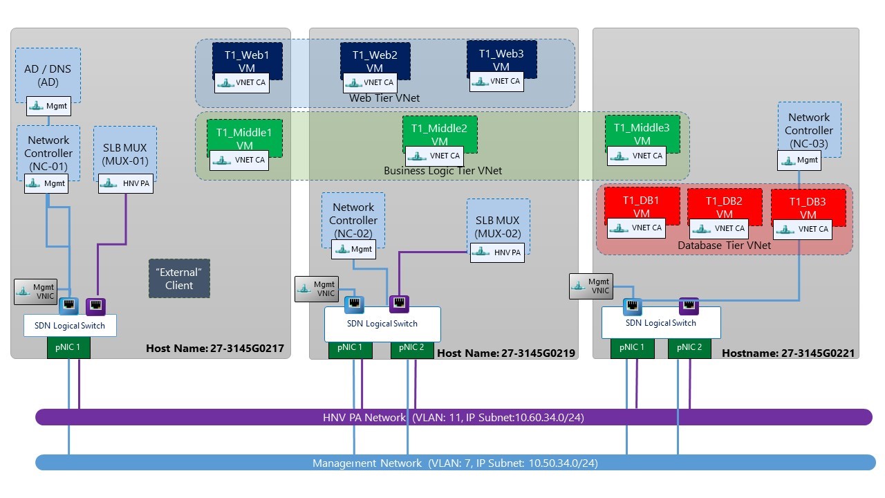
The first step in deploying the cloud application is to install and configure the servers and infrastructure. You will need to install Windows Server 2016 Technical Preview 4 on a minimum of three physical servers. Use the Planning Software Defined Networking TechNet article for guidance in configuring the underlay networking and host networking. The environment I used while writing this post and deploying the three-tier app has the following configuration:
Enterprise and hosting providers use their IT tool kits to address similar and reoccurring problems:
Windows Server 2016 helps you address these challenges in the application platform itself, and for the networking technology we’ll cover in this blog it’s the same technology that services the 1.5 million+ network requests per second average in Microsoft Azure.
The scenario for the series is for a new product that our fictitious firm “Fabrikam” is launching to meet the demands for convenience and self-service in requesting a new passport, renewing an expired passport, or updating a citizen’s personal information. The application is called “Passport Expeditor” and it removes the need for a citizen to go to the passport agency and execute a paper-based process that uses awkward government-speak.
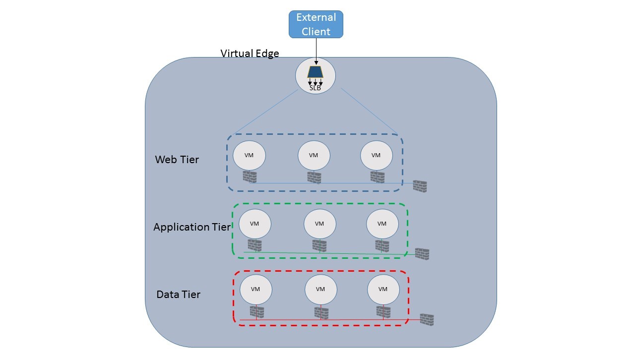
Passport Expeditor is based on a three-tier architecture, which consists of a front-end web tier to present the interface to the user, the application tier to validate inputs and contains the application logic, and a back-end database tier to store passport information. The software in each tier runs in the in a virtual machine, and is connected to one or more networks with associated security policies.

Figure 1: Passport Expeditor application architecture
External users will access Fabrikam’s Passport Expeditor cloud application through a hostname registered to an IP address that is routable on the public Internet. In order to handle the thousands of requests Fabrikam expects to see at launch, load balancing services are required and will be provided in the network fabric using Microsoft’s in-box Server Load Balancer (SLB). The SLB will distribute incoming TCP connections among the web-tier nodes providing both performance and resiliency. To do this the SLB will monitor the health probes installed on each VM and take any VMs which are “down” out of rotation until they become healthy again. The SLB can also increase the number of VMs servicing the application during periods of peak load and then scale back down when load decreases.
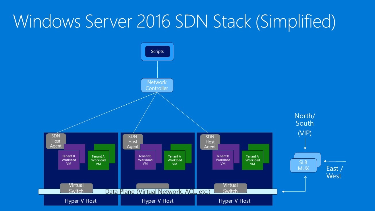
Before we dive in, let’s spend a moment talking about some core concepts and technologies we will be using:

Figure 2: Windows Server 2016 SDN stack
Perform the following steps to configure Windows Server Technical Preview 4 for the scenario:
The system is now ready to receive the SDN Stack components, software infrastructure, and inform the Network Controller about the fabric resources. If you haven’t already retrieved the scripts from GitHub, download them now. All scripts are available on the Microsoft SDN GitHub repository and can be downloaded as a zip file from the link referenced (for more details on Git, please reference this link).
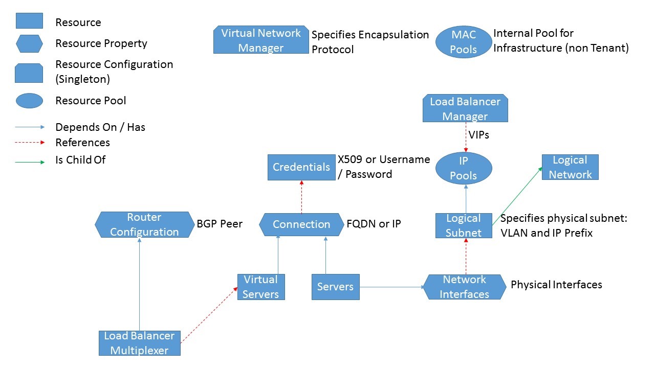
The Network Controller must be informed of the environment it is responsible for managing by specifying the set of servers, VLANs, and service credentials. These fabric resources will also be the endpoints on which the controller enforces network policies. The resource hierarchy and dependency graph for these fabric resources is shown in Figure 3.

Figure 3: Network controller northbound API fabric resource hierarchy
The variables in the FabricConfig.psd1 file configuration file must be populated with the correct values to match your environment. Insert the appropriate configuration parameter anywhere you see the mark “<<Replace>>”. You will do this for credentials, VLANs, Border Gateway Protocol Autonomous System Numbers (BGP ASNs) and peers, and locations for SDN service VMs.
When customizing the FabricConfig.psd1 file:

Figure 4: Deployment environment
After customizing this file and running the SDNExpress.ps1 script documented in the TechNet article, validate your configuration by testing that the requisite fabric resources, e.g. logical networks, servers, and SLB Multiplexer, are correctly provisioned in the Network Controller by following the steps in the TechNet article. As a first step, you should be able to ping the Network Controller (NetworkControllerRestIP) from any host. You should also verify that you can query resources on the Network Controller using the REST Wrappers Get-NC<ResourceName> (e.g. PS > Get-NCServer) and validate that the output includes provisioningState = succeeded.
Note: The deployment script creates multi-tenant Gateway VMs. These will not be used in this blog series.

Figure 5: Network controller provisioning
The final check is to ensure that the load balancers are successfully peering with the BGP router (either a VM with Routing and Remote Access Server (RRAS) role installed or Top of Rack (ToR) Switch. Border Gateway Protocol (BGP) is used by SLB to advertise the VIP addresses to external clients and then route the client requests to the correct SLB Multiplexer. In my lab I am using the BGP router in the ToR and the switch validation output is shown below:

Figure 6: Successful BGP peering
In this blog post, we introduced the Passport Expeditor service which can be installed as a cloud application using the new Microsoft Software Defined Networking (SDN) Stack. We walked through the host and network pre-requisites and deployed the underlying SDN infrastructure, including the Network Controller and SLB. The fabric resources deployed will be used as the basis to instantiate and deploy the tenant resources in part II of this blog series. The Network Controller REST Wrapper scripts can be used to query the fabric resources as shown in the TechNet article here.
In the next blog post: Front-end Web Tier Deployment and Tenant Resources
The SDN fabric is now ready to instantiate and deploy tenant resources. In the next part in this blog series, we will be creating the following tenant resources for the front-end web tier of the three-tier application shown in Figure 1 above:
We’d love to hear from you. Please let us know if you have any questions in the comments!